More actions
m (Text replacement - "Category:Other GBA applications" to "") |
|||
| Line 55: | Line 55: | ||
[[Category:GBA homebrew applications]] | [[Category:GBA homebrew applications]] | ||
Revision as of 04:17, 10 Mayıs 2024
| Vero Design Advance | |
|---|---|
 | |
| General | |
| Author | Mike Hawkins |
| Type | Other Apps |
| Version | 1.0 |
| License | Mixed |
| Last Updated | 2007/11/18 |
| Links | |
| Download | |
| Website | |
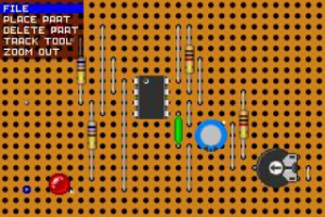
Vero Design Advance is a CAD package designed to help you layout Veroboard/stripboard designs on your Gameboy Advance.
User guide
Basics
When you first start the program, you will see a blank bit of Vero or stripboard. At the bottom left side of the screen are the current cursor co-ordinates relative to the entire board area that can be edited. Effectively this is the X,Y of the hole on the board at which the cursor is positioned.
Root menu:
- File - New/Clear board, Load and Save (6 save slots, filenames can be up to 24 characters).
- Place Part - Select a component to place. You can flip the part but not the board in this mode.
- Delete Part - Delete a placed component. All associated track cuts and solder joints will also be removed.
- Track Tool - Cut or repair a track.
- Zoom out - Shows the entire board are (60 x 40 holes).
Placing parts
Axial parts (Diodes, Resistors and Wire links) have a variable span. This is achieved by pressing the B button when you have an axial part as the current floating selection. Maximum span for these parts has been set at 18 holes after which the span will default to the specific components minimum span (Res and Rect diode = 5, Signal and Zeners = 4 and wire links 2 holes).
When placing a resistor, you will be prompted to define it's value. Use D-Pad to change the bands on the large resistor shown and press A when done. You can opt not to specify a value by pressing B. If you select 0 (Black) as the first band, the program will interpret the value 0 ohm.
Note: It is possible to enter some weird and wonderful values that certainly aren't in the preferred value list. Also, you cannot enter values below 1 ohm. The program also cuts any required tracks (eg between IC pins) and adds solder joints to solder side of board.
Controls
D-Pad - Cursor
R - Flip to the solder side
L - Root menu
A - Action key
Track tool:
A - Toggle cut or uncut at the cursor position on the board hole
